Introduction
This step-by-step tutorial will show you how to assemble the RK-micro:bit robot, which is a differenial robot chassis with a micro:bit as its controller.
We will have another tutorial to inroduce how to program this robot using MakeCode
| author | 楊國立 (intern) | ||
| Time | 1~ 2 hours | BOM | |
| Difficulty | 3 / 5 | ||
Content
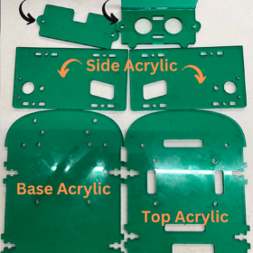
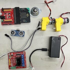
First we check the meterial needs for this RK-micro:bit robot.
| —Micro:bit*1 —L298n motor driver module*1 —TT Motor*2 —Ultrasonic(HC-SR04)*1 —Ball wheel*1 —65x15mm wheel*2 —9VBattery Holder with On Off switch*1 —Micro:bit Sensor shield module*1 —Micro USB Wire*1 —M3*8 Screw*2 |
—M3*12 Screw*10 —M3 Nut*12 —M2*20 Screw*4 —M2 Nut*4 —M3*6 Plastic Spacer*10 —M3*6 Plastic Screw*10 —M3 Plastic Nut*10 —Acrylic sheet*1 —10p Wire |
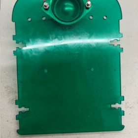
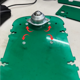
STEP 1 Attach the front wheel to the base board (Base Board x1,M3*8 Screw x2,M3 Nut x2) (It’s the same which side you attach)
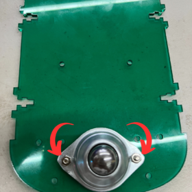
STEP 2 Attach (m3x6)x4 to the base board(m3x6)x4 (Attention: Place it in the right direction, the screw is the same side with the ball wheel)
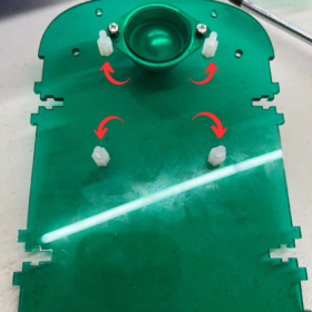
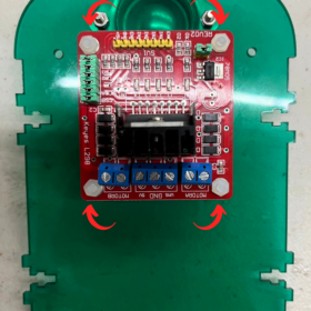
STEP 3 Attach the L298n motor driver module above the base board (Attention to the direction of the motor driver)
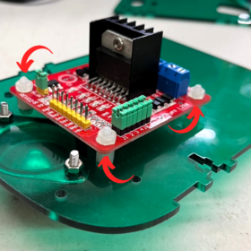
STEP 4 Attach the cables from 2 motors, 9V Battery Holder with On Off switch & Micro USB Wire
– Motor B {Left} the most left side is black cable and then the right one is red cable
– Motor A {Right} the most right side is black cable and then the left one is red cable
– Put the USB red cables in the middle on the most left side
– Put the battery red cables in the middle on the most right side
– At the middle of all of it put both battery & USB black cable together
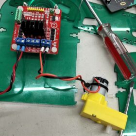
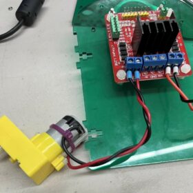
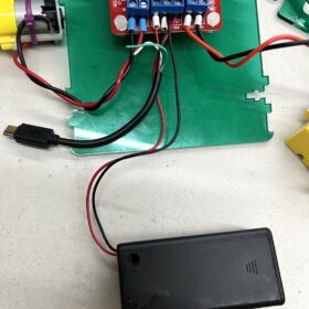
STEP 5 Attach the Motors to the side acrylic (Aware fo the direction)
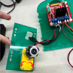
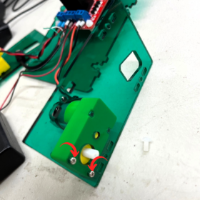
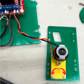
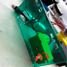
STEP 6 Attach the side body to the base acrylic (Attention: do not tighten the screws yet)
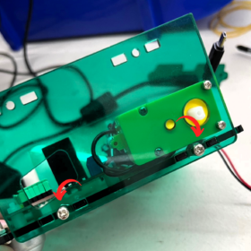
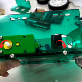
STEP 7 Attach the ultrasonic sensor to the Ultrasonic acrylic board. Use (m3x6) x2.
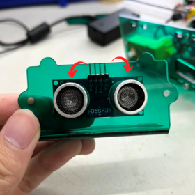
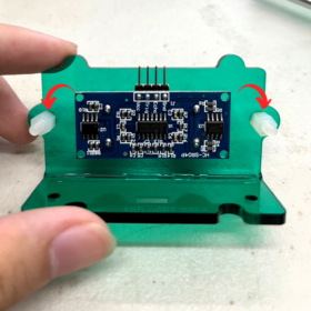
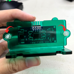
STEP 8 Attach the ultrasonic acrylic to the base acrylic (m3x12)x2 (Attention: Attach it ABOVE the base acrylic, not under!!)

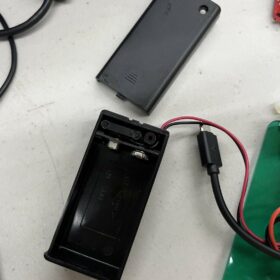
STEP 10 Put the 9VBattery Holder with On Off switch between the top acrylic (Open the battery holder first so it will fit)
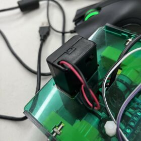
STEP 11 Pull the USB cable over the top of the acrylic

STEP 12 Plug the cables based on the pictures

STEP 13 Pull the cables over the top of the acrylic based on the picture

STEP 14 Attach top board with (m3x6) x4
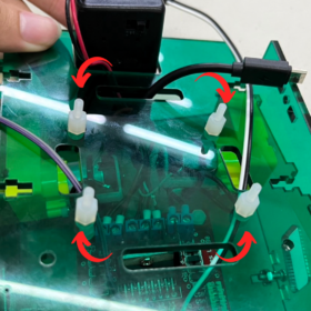
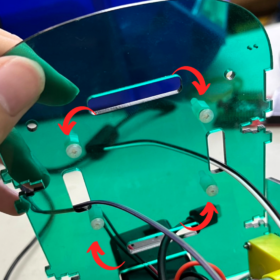
STEP 15 Attach the top acrylic to the rest of the body and lock all the screws firmly
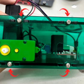
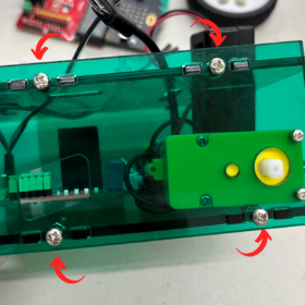
STEP 16 Attach the above the micro:bit sensor shield module top acrylic (Aware of the direction of the micro:bit sensor shield module)

STEP 17 Attach the both wheels
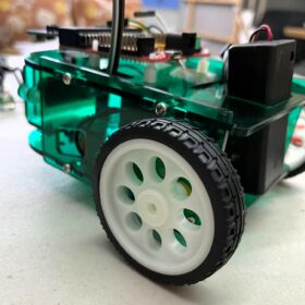
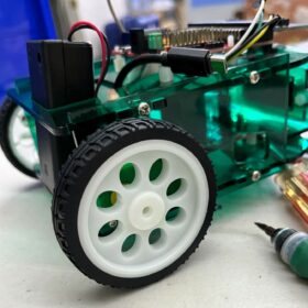
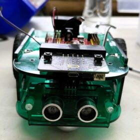
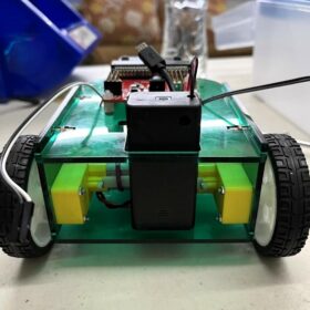
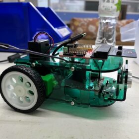
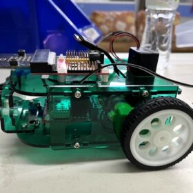
Finished!
Feel free to adjust all the settings, add more of your own creativity to make it better! We will have another articale to show you how to control this robot by MakeCode graphical IDE.
〈RK-micro:bit robot – assembly tutorial〉這篇文章最早發佈於《CAVEDU教育團隊技術部落格》。